C-CORP 1310 Optical Transmitter Direct Modulation
C-CORP 1310 Optical Transmitter Direct Modulation is a strong technical professional equipment, its installation and commissioning must be carried out by professional and technical personnel and carefully read the manual before operation, so as not to damage the equipment due to wrong operation, or cause accidental injury to the operator.
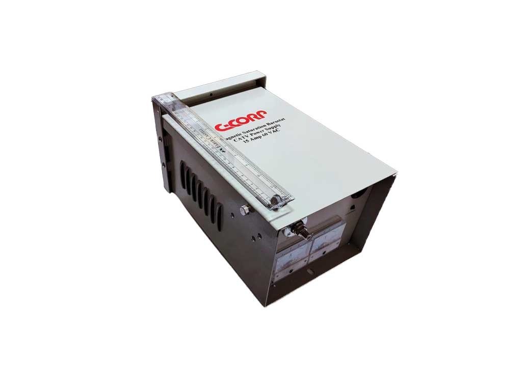
C-CORP 1310 Optical Transmitter is designed according to CATV standard. It modulates CATV RF amplitude signal into 1310nm optical signal and then transmits it to optical node in HFC network through single-mode optical fiber. It is mainly used for TV signal medium-sized network transmission.
When the device works, the optical fiber adapter which is located in the rear panel cannot be visible in the optical fiber adapter. The optical signal output port is not aligned with the human body, and the optical output port cannot be looked directly at the eye, so as to avoid permanent damage to the human body and the human eye (the laser can cause blindness)!!!
Before setting up the equipment, the operator should ensure that the system rack and power sockets grounding terminal has a reliable grounding (grounding resistance should be less than 4Ω), in order to avoid damage to the static laser devices and to prevent the body from electricity shock.
In order to ensure long-term stable operation of the equipment, it is recommended for the user to configure a dedicated AC regulated power supply. It is recommended that this is to be used with uninterrupted power supply (UPS) system (equipment ideal working environment temperature is 25 degrees Celsius) and it is recommended that there a good air-conditioning to improve the working environment of the equipment.
1.)Product Structure
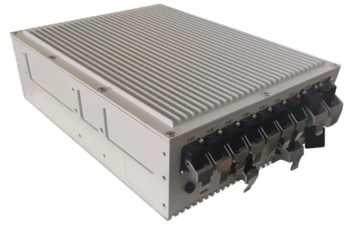
- Product Overview This C-CORP 1310 Optical Transmitter Direct Modulation is designed to meet the requirements of a front-end computer room equipment intensive installation, development and design of a CATV integrated node. The double power supply hot backup structure feature is dedicated to the server and can effectively improve the reliability of the system with the intelligent temperature control system controlled by the microcomputer. The device is equipped with a standard RJ45 network communication interface (built-in responder), 10/100Mbps adaptive rate, can easily achieve remote network management centralized monitoring, is to build a high-performance two-way HFC broadband network of the first choice. Can be equipped with modules: dual module combination or single module independence.
- Product Feature
* Compact design, 1U rack can be achieved dual module integration.
* Configuration flexible, on-demand collocation.
* 32 bit ARM architecture of the control unit, the robust CPU can be real-time monitoring of each module within the framework of the operating parameters.
* The utility model is convenient and practical. It can adjust the level and the slope of the target module through the front panel function button or the network management system.
* The structure of the double power supply is used to match the intelligent temperature control system which is controlled by the microcomputer, which can improve the reliability of the system.
* Equipped with the standard RJ45 network management communication interface, it can easily realize the centralized monitoring and control of remote network management. - Diagram

- Panel Description

Pump laser switch: This switch is a lock switch, when the key is used to transfer the lock to the OFF position, the pump laser will be switched off when the key is directed to the ON.
USB: This port for the USB micro interface, serial communication, for the debugging interface.
RJ45: Network interface, you can use this network to connect the network management, the device access to the network management, equipment model for Platform_1U.
Display: Display device menu
Key:
↺ : Cancel
▲:Move up
▼:Move down
↵ : Shift
Power: Double power supply for the green light and single power supply for the orange light.
MOD1: When the lamp is bright, the module is in the presence of a module. When the lamp is green, the module is working normally.
MOD2: When the lamp is lit in the presence of two modules: when light is green Module II is working properly and there is a red alert when the module II is not working.
Temp: This lamp is a temperature indicator. A temperature alarm occurs when red and green if normal. - Network Configuration Instructions
The default network parameters of the device is
IP:192.168.0.160
Mask:255.255.255.0
Gateway:192.168.0.1 - Equipment Type

Module referred to corresponding table:| RF Amplifier | FA |
| Forward Optical Receiver | FR |
| Upstream optical transmitter | RT |
| RF Switches | R S |
| Direct Modulated Optical Transmitter | LT |
| EDFA | EA |
| Optical Switch | OS |
2.)Product Structure
- Model Description

- Diagram

- Technical Data
| Project | unit | Technical Data |
| Output power | mw | 2mW-30mW or 3dBm -10dBm |
| Wavelength | nm | 1310±20 or 1550±20 |
| Laser | | DFB laser |
| Light Modulation | | Direct light intensity modulation |
| Optical connector | | SC/APC or SC/UPC |
| bandwidth | MHz | 47 ~ 1000MHz |
| EF Input Level | dBµV | 70 ~ 90 (better80dBµV) |
| Flatness | dB | ±0.75 |
| Monitoring port level | dBµV | -10 (Input) |
| Inputs isolation | dB | ≥50 (Local port to broadcast port) |
| AGC Accuracy | dB | 0.25 |
| MGC adjustment range | dB | 0 ~ 15 |
| RF input impedance | Ω | 75 |
| Input Return Loss | dB | ≥16 |
| C/CTB | dB | ≥65 |
| C/CSO | dB | ≥60 |
| CNR(C/N) | dB | ≥51 |
Note: The above technical parameters are in accordance with the technical requirements and methods of measurement GY / T 143-2000 predetermined measured.
- Menu Operation
Parameter Display Menu Contents:Level IN: input signal levelOMI Set: modulation level settingLaser Out: output powerBias Current: bias currentChip Temp: die temperatureCool Current: cooling currentModule: module temperature
Set Menu Content:
Content Mode: work mode, AGC, MGC switch
OMI Set: modulation level
Power Set: power setting
Level Set: level setting
RF ATT: Attenuation amount
SUB ATT: Attenuation roads
3.)Installation and Debugging
● Before unpacking the device make sure the packaging is intact; if found damaged packaging or water marks, please contact us.
● Make tank inventory verification equipment and accessories in accordance with the packing list after unpacking, any questions please immediately call the company directly.
● If you believe the device is damaged, do not open, so as to avoid more severe damage to the equipment, or accidental injury to operating personnel after unpacking; and immediately call the company directly.
4.)Maintenance and Troubleshooting
This C-CORP 1310 Optical Transmitter Direct Modulation has been tested at the factory with careful commissioning. Please check the following table when the control is not working properly, if found with machine malfunctions, please contact our sales department or sales department. Do not reboot to repair, otherwise the warranty will be void.
| Issue | Cause | Solution |
| After the device powered on, the front panel display and lights are off. | Switching power supply does not start normally. | Replace Power supply |
| RJ45 network cable network after the access barrier, a network connection is not on. | Transponder IP address and IP address of the computer is not connected to a network segment. | Read the instructions carefully NMS NMS transponder will change the IP address and computer IP addresses in a network without IP address. |


Explore more products when you click here.
You may also like and follow our Facebook Page: Clusterasia Corp. for more updates.


Reviews
There are no reviews yet.